20+ generator block diagram
Begin by opening a Creately workspace you can make edits to multiple pre-made templates or start creating your block diagram from scratch. This is done by an RF.
1
This oscillator will be a well.
. The common output waveforms are the sine square triangular and sawtooth waves. Function Generator Block Diagram. ADRC developed by Han in 1995 18 and modified by Gao 181920 is proposed for the LFC controller 21 22 23.
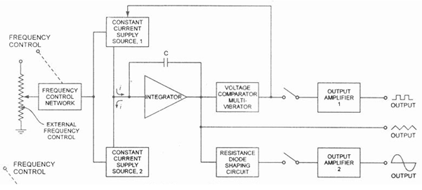
The frequency control network is governed by the voltage applied externally or the frequency dial provided on the front panel of the device. It makes RF signal generators a valuable tool for testing. A Function Generator Block Diagram produces different waveforms of adjustable frequency.
The filter arrangement controls the bandwidth and supplies an output signal in three spectrum choices white noise pink noise and Usasi noise in the random noise generator. Block Diagram of Arbitrary Waveform Generator. Each block can be toggled on or off by clicking the respective icon on the block diagram.
Block Diagram Working Principle and Construction of Signal Generator Video Lecture of Analog and Digital Instruments Chapter in Subject Electronic Instrumen. For instance if you are playing waveforms you can stop one waveform while allowing another to. Source Basics 2000 Applications Critical Specifications Amplifier Compression Power In P o w e r O u t 1 dB compression.
Functional Software Electrical etc. Ad Templates Tools To Make Block Diagrams. Identify all the components inputs and.
-20-10-5 0 5 Abs dB Ch1 Who Cares About Accuracy. It is an emerging controller. Working of AMFM.
Block Diagram of Generator and Load. Signal is generated from 100 kHz to around 200 MHz. Arbitrary Waveform Generator is a waveform generator which generates waveforms based on digital data stored in RAM.
Also in the function generator block diagram a voltage comparator and multi-vibrator device is used where this triggers a change in the phase of the output voltage at the. RF signal generators produce sinusoidal and pulse-modulated RF signals with an arbitrary waveform and modulation.

Block Diagram Of The Solar Generator System Download Scientific Diagram

17 Ghz Ism Wlan Rf Frontend Block Diagram 19 20 Download Scientific Diagram
Block Diagram The Generator Side Control Download Scientific Diagram

Block Diagram Of The High Frequency 20 Ghz Phase Stabilizer 4 Download Scientific Diagram

Fig S2 Detailed Schematic Diagram A Microwave Generator Creates A Download Scientific Diagram
1

Simplified Block Diagram Of The Square Wave Pulse Generator Hv Download Scientific Diagram
Function Generator Circuit Diagram Using Lm324 Ic Its Specification

Pins Cd4013

Block Diagram Of The Low Frequency 20 Ghz Phase Stabilizer 5 Download Scientific Diagram

The Circuit Diagram Of A Typical Marx Generator To Meet Hemp Protection Download Scientific Diagram

Schematic Of Pulse Generator For Micro Ecm 20 Download Scientific Diagram
1

Block Diagram Of The Low Frequency 20 Ghz Phase Stabilizer 5 Download Scientific Diagram
1

Circuit Diagram For The Variable High Voltage Power Supply Which Is Download Scientific Diagram
Main Circuit Diagram Of Signal Generator Download High Resolution Scientific Diagram